Allen 'Princess' Pedalboard MIDI Conversion |

|
|
This project was the first step in converting a late `50s vintage Allen Organ Company T-3 Analog organ into a MIDI controller for use with the Hauptwerk virtual pipe organ software. The client wanted to be able to use the pedalboard as a stand-alone MIDI controller so an independent MIDI encoder was used. Additional MIDI and power jacks were added since the pedalboard would be moved frequently between the Allen console and other MIDI setups.
Follow along as the conversion process is described in detail.
|
|
|
|
|
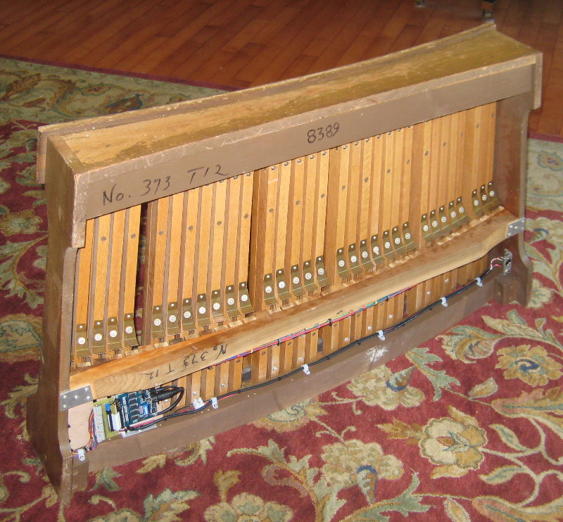
The picture above shows the (completed) underside of the pedalboard. The switches on this pedalboard are typical of organs with electic switching be they pipe or electronic and consist of 'contact blocks' and 'contact plates'[1]. The contact blocks are mounted on the horizontal rail across the width of the pedalboard about one fourth of the was back from the 'console' end. Each contact block is positioned under a contact plate which is screwed to the bottom side of a pedal key. The contact blocks on this pedalboard have four individual contacts. When a pedal is depressed the contact plate shorts (connects) all the individual wires in the contact block. Here's a shot of the contact arrangement:
|

|
|
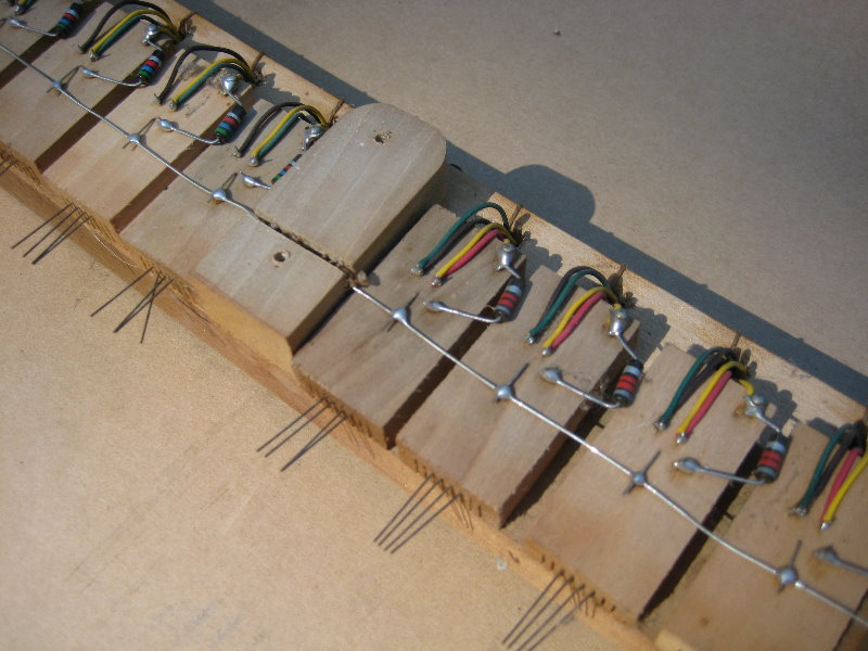
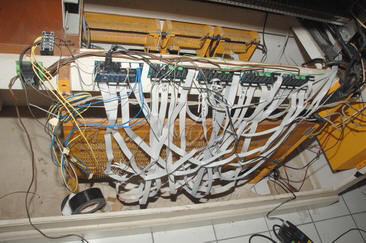
As delivered there was a multi-conductor bundle of wires leading from the contact rail. As the wiring included analog components (resistors) for the original sound production system the decision was made to rewire the contacts. The following picture shows the original wiring:
|
|
|
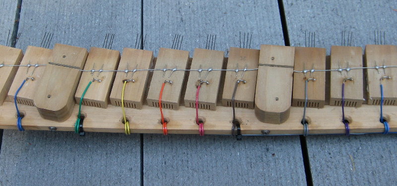
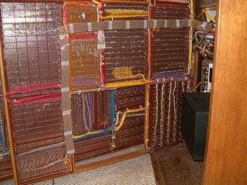
In the above picture you can see that one wire from each contact was connected to a bus wire or 'common' for all the keys. The other 3 contacts had a total of 5 connections. The bundle of wires leading from the pedalboard to the console had well over 100 wires! [2] Here's shot of the rewired contact rail:
|
|
|
After carefully unsoldering all the original wiring and resistors a second contact on each block was soldered to the common wire. A new wire for each key was soldered to the remaining two contacts. The use of multiple contacts per wire gives additional reliability to the pedalboard. I used 8 different wire colors and kept the four bundles of eight separate until wiring the encoder. The wire colors follow the Resistor Color Code. To keep things neat the new wires were wrapped through the existing guide holes and a cable tie was used every 4 holes or so to keep the bundled wires close to the rail.
|
|
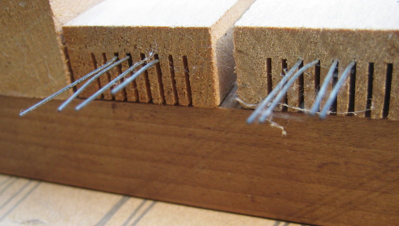
While the contact rail is out of the pedalboard take the opportunity to clean and carefully straighten the contact wires. Several on this pedalboard needed adjustment.
|
|
|
Encoder SelectionMIDI encoders use two different methods for wiring switches, parallel and matrix[3]. Since I was rewiring from scratch I could have chosen either method. But since a pedalboard only requires 32 wires (vs 61 for a keyboard) the disadvantage of the parallel method is out-weighed by the simplicity of the wiring. For this project I chose the mpc32xrs from MIDI Gadgets Boutique.
|
|
|
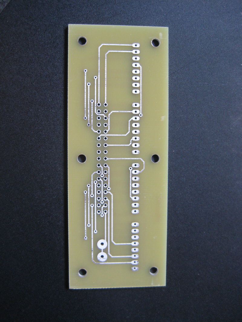
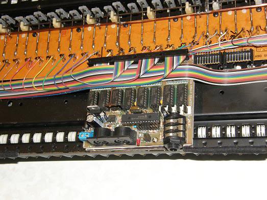
This encoder has 40 total switch inputs which cover the 32 keys of the pedalboard, 3 spare inputs (toe studs?), and 5 dedicated inputs for software control (which I didn't use in this application). The intention is to use ribbon cable between the encoder board and the switches on the pedalboard but I personally don't like ribbon cable wiring in organs although it can be done neatly. To that end I built a 'transtition board' to go between the ribbon cable idc connector on the mpc32xrs and the individual wires I used to rewire the contact blocks.
|

|
|
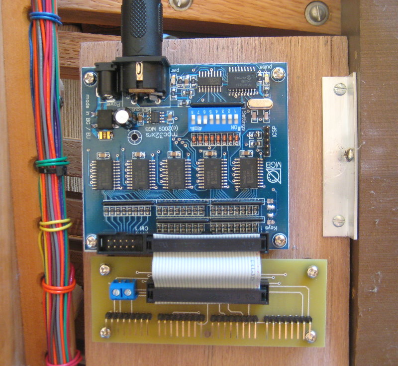
A small piece of lauan plywood was used to mount both the mpc32xrs and the transition board. I drilled holes in the lauan and mounted the boards on 1/4 inch standoffs (spacers). I then mounted the lauan under the front right corner of the pedalboard using two short pieces of aluminum angle for support.
|
|
|
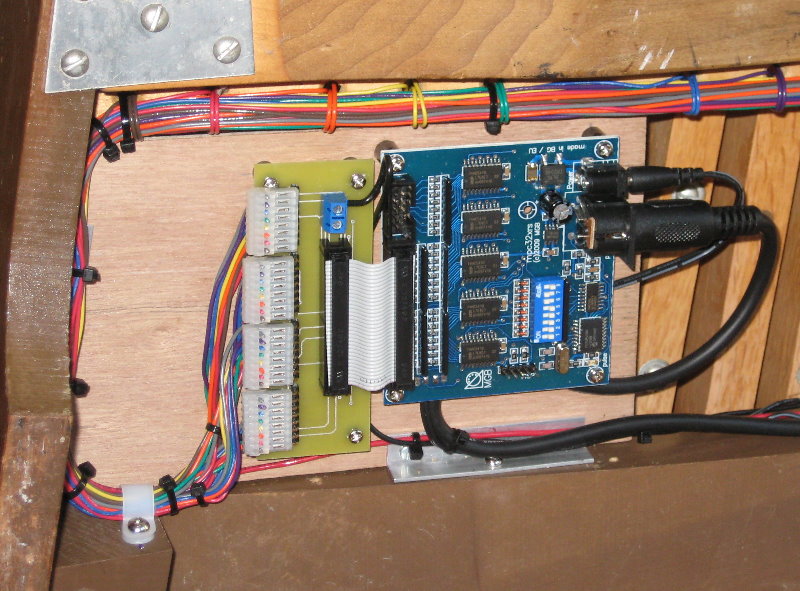
Each group of 8 wires from the contact blocks was punched down onto an insulation displacent connector (IDC). These Panduit connectors area available from Classic MIDI Works and Klann Organ Supply among other outlets.
|
|
|
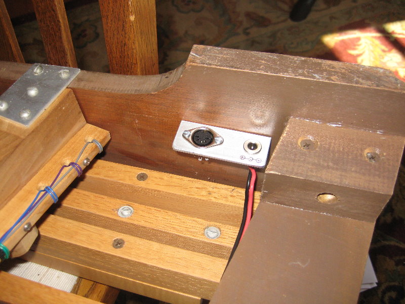
Since this pedalboard was going to be used in multiple setups which would require frequent plugging and unplugging of both the MIDI and power connectors I added auxilliary connectors to eliminate the plugging/unplugging stress from the mpc32xrs. Using another piece of aluminum angle I mounted a MIDI connector and a power connector on the left side of the pedalboard. I cut the the end off of a MIDI cable and wired it between the new connector and the mpc32xrs. I did the same with a power cable.
|
|
|
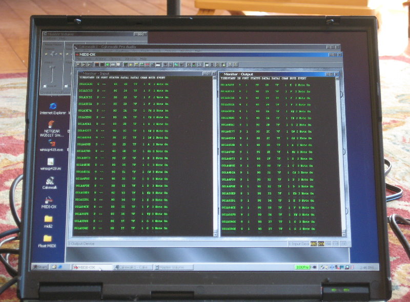
Cable clamps were used to secure the various cables and keep them tidy. With the wiring complete the MIDI-OX utility was used to test the operation.
|
|
|
That completes the project. I hope that this will give you a good idea of what is involved in doing a conversion like this. I doubt your project will procede exactly as I've described here, your needs are likely different. If you have questions or comments I be contacted HERE
|
|
|
Notes:[1] The terms 'contact block' and 'contact plate' are from the Organ Supply Industries catalog of console parts. See page O-22.
[2] Had I chosen to retain the original wiring I would have 'buzzed out' the circuits in the cable with a continuity tester. On this pedalboard you would choose one contact on each block and test for continuity between it and the other end of each wire in the bundle. When the wire is identified it is labelled. This pedalboard would be easier to 'buzz out' than most because the wires have colored insulation which gives you a starting point at the other end of the cable. Frequently, all the wires will be the same color. This pedalboard is modern enough that the existing wiring could be confidently reused. Older pedalboards (especially from pipe organs) are frequently wired with wire having a cotton and wax insulation that does not age well and short circuits between wires are a real possibility. Additionally, the National Electrical Code (NEC) requires that this wire be replaced if work is to be 'to code'. [3] Parallel wiring generally connects one pole of all the switches together with one wire, the 'common'. Individial wires from the other pole of all the switches are connected to separate inputs on the encoder board. For a pedalboard this requires 33 wires, 32 keys plus the common. With a keyboard it requires 62 wires and the cable starts to become unmanageable. Matrix wiring arranges the switches into an array. There is a schematic here: Kens Mame Project. For a 4x8 matrix (32 notes) only 12 wires are needed. For a keyboard the matrix expands to 8x8 or 16 wires. However the wiring is more complicated, diodes need to be added, and troubleshooting can be trickier. |
|
Copyright © 2013 - John Haskey - Information on this site may be copied for educational use only.
|