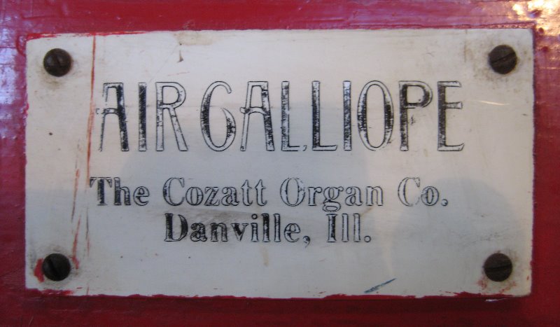
Cozatt Air Calliope
Cozatt Organ Company
Danville, Illinois
|
This page documents the refurbishment of a Cozatt Air Calliope Model No. 1.
The instrument was built by the Cozatt Organ Company of Danville, Illinois.
According to Billboard Magazine (April 7, 1958) Perry Cozatt, an established
organ builder began making calliopes in the 50s:
"There are other calliope plants in action now, most of them operated by
men who are perfecting their own models. One of these is Perry Cozatt
of Danville, Ill. Another is Dowell M. Singer of Decatur, Ind. There
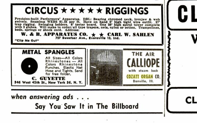
have been others in recent years. Cozatt also advertised in Billboard Magazine, here's an ad from 1960:
The Mechanical Musical Digest at Foxtail.com has a scan of an orginal
Cozatt Calliope Catalog in its Gallery and can be found here: I hope to add more information about the Cozatt Calliope and their history. If you have any additional information please contact me.
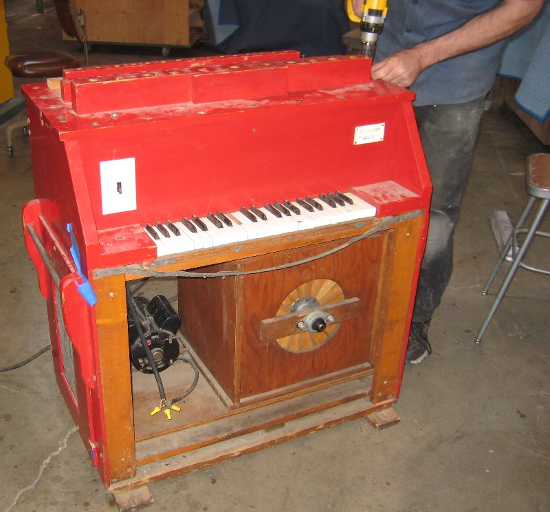
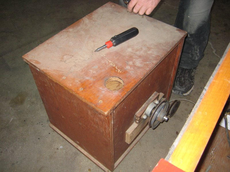
Disassembly of the base unitAfter removing the whistles and the front and back covers of the unit we are left with this:
It's not clear if the handles on the sides are original. Pictures of other Cozatt calliopes show a different style of handle.
I have no idea how many people have been inside this instrument since it left the factory but the construction appears to be a bit crude to say the least. It's clear by inspection that some modifications have been made over the years. There are three main sections, the bottom contains the blower and motor, the center section contains the keyboard and action, and the top section houses (essentially *is*) the windchest. Like most (all?) calliopes there is no air pressure regulator. As more notes are played the air pressure and thus the pitch of the whistles drops adding to the characteristic calliope sound. In the rear view you can see the cardboard tube (at left) that conveys the wind from the blower to the windchest.
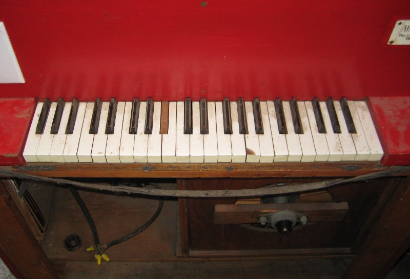
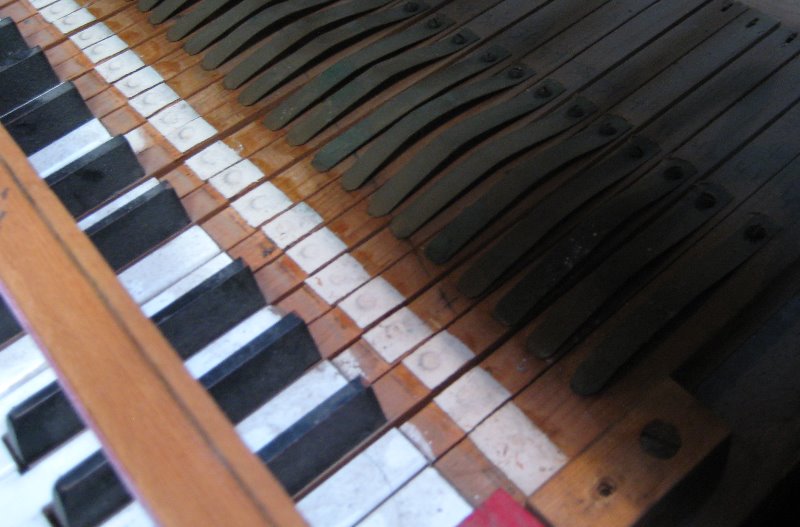
This particular instrument has 44 keys playing 44 whistles. You can see that some work will be required to rehab the keyboard. One sharp is missing and the plastic 'ivory' is chipped on another. Not to mention several years of dust from storage.
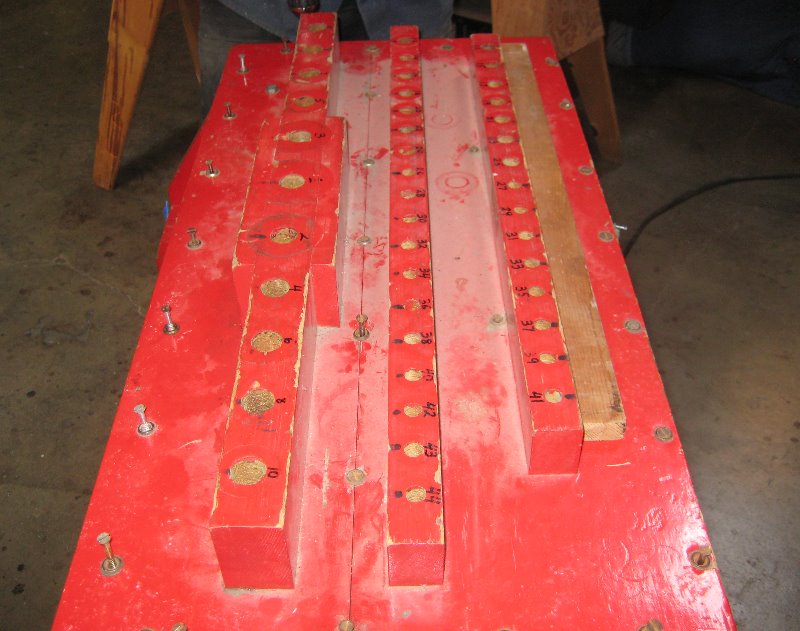
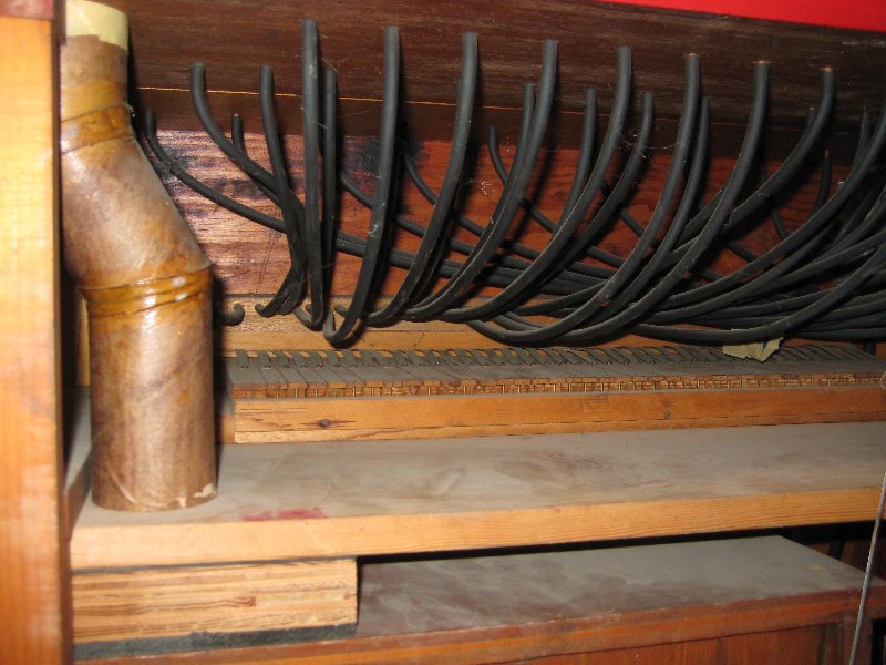
This top view shows the holes that the whistles sit in. The row on the left supports the bass pipes with the lowest (longest) note in the center. The two rows on the right support the treble pipes in decreasing size from far end to near end alternating from row to row. Note 44 (the highest treble whistle) is closest to the camera. The existing fit is somewhat 'sloppy' and we'll be looking at adding some gasket material to help eliminate wobbles and wind leaks around the whistle 'feet'. (The wood lying next to the rightmost row is not part of the instrument as far as we can determine. It was found loose inside the lower case.)
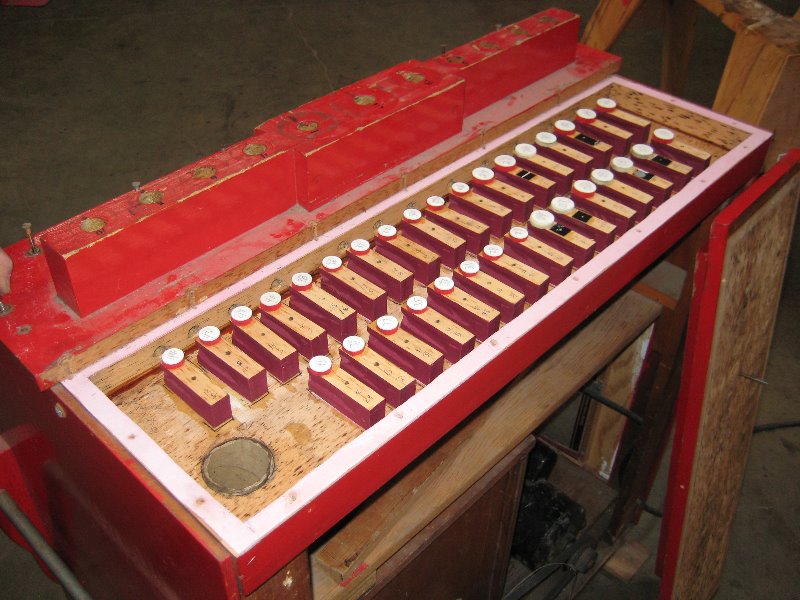
Removing the treble supports we can see the pneumatics that are positioned under each whistle. When one of these pneumatics collapses, air is allowed into the corresponding whistle. The hole in the lower left is the passage through which air enters the chest from the blower. In the rail between the treble and bass supports you can see holes that allow the air to pass from one side to the other.
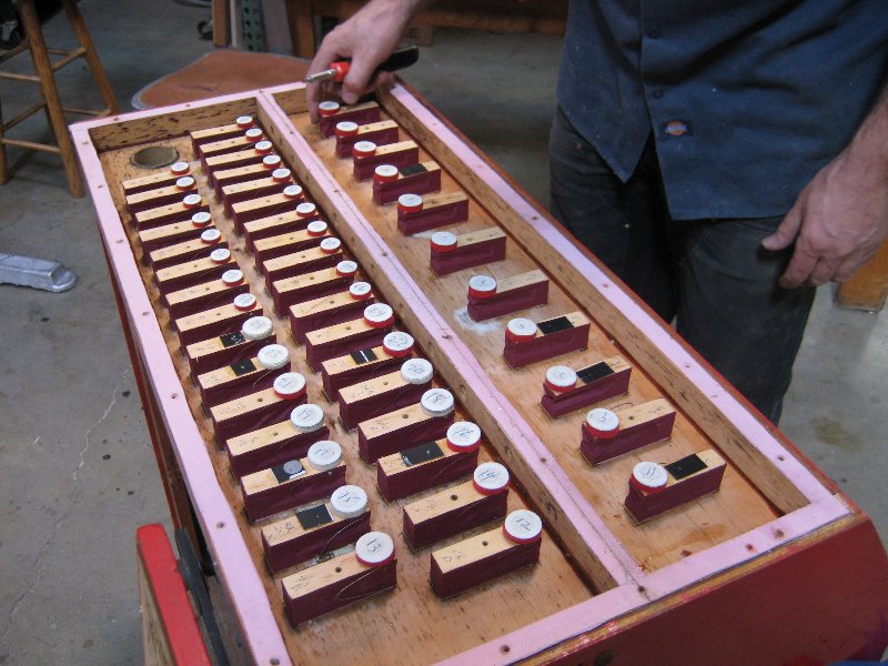
With both the bass and treble supports removed you can see all the pneumatics. Thankfully, they all are in decent condition and in fact all the notes are working except for one that is a little slow to react.
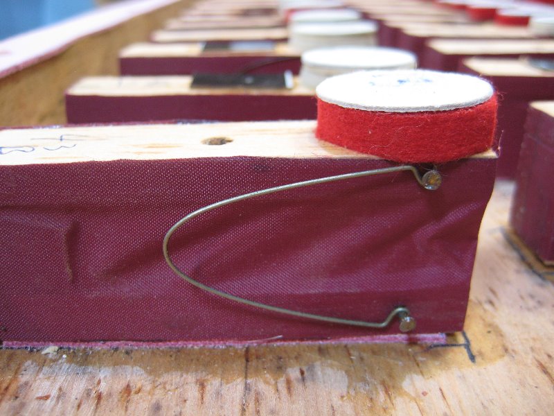
Here's a closeup shot of one of the pneumatics showing the return spring and the felt and leather pad that covers the hole leading to the 'foot' of the whistle. The hole in the top to the left of the pad is the 'bleed' which allows chest pressure to equalize the pressure inside and outside the pneumatic.
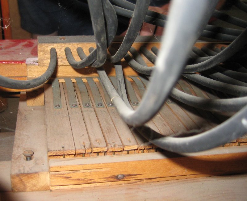
Here's a shot of the middle section of the case from the back showing the tails of the keys and the tubing from the bottom of the windchest above and the touch box above the keys.
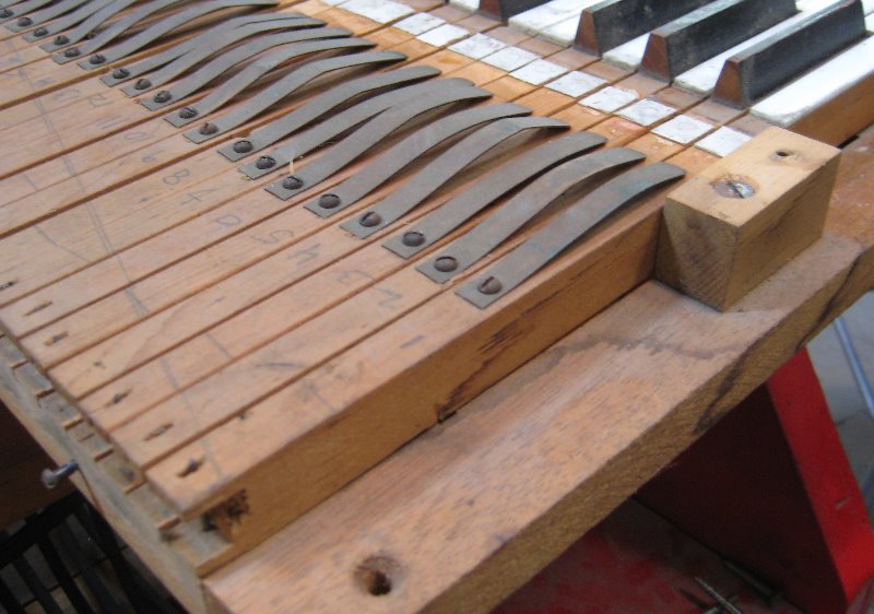
Here's a closer shot of the treble end of the keyboad. The tubing connects each pneumatic in the windchest to a hole in the touch box above the corresponding key. The metal strips screwed to the top of the keys are phosphor bronze springs that return the keys to the 'up' position when they are relased.
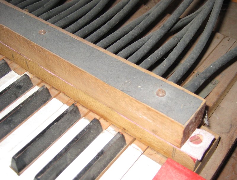
This is the front/top of the touch box. The top rail holds the ends of the tubes. This rail is separate and can be removed if you want to reomove the keys and keybed as a single assembly.
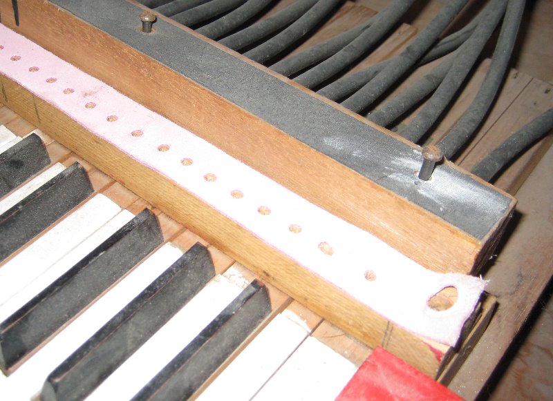
The top rail unscrewed and moved slightly to the rear exposing the gasket material between the two rails.
With the lower rail removed and placed on the sharps the leather 'buttons' that cover the holes in the bottom of the touch box are visible. When a key is depressed the hole in the touch box is uncoverd. This opens the tube to atmospheric pressure. The dark line along the lower edge of the rail is the slot that the key return springs fit into.
The key tails and key frame removed from the calliope.
Operation of the ActionSurprisingly the action is quite simple. With the blower on and the key at rest in the up position, the pressure inside the pneumatic is the same as the pressure surrounding the pneumatic due to the small hole in the top of the pneumatic (seen in the closeup photo above). When a key pressed, the inside of the pneumatic is now open to the outside air through the tube. The air in the pneumatic exhausts through the tube faster than the hole in the top of the pneumatic can recover and the increased pressure inside the windchest causes the pneumatic to collapse uncovering the inlet to the whistle. When the key is released, air can no longer escape from the pneumatic and as the pressure inside increases amd equalizes with the chest pressure the small spring is able to push the pneumatic closed and thus covers the inlet to the whistle once again. Clear as mud, right? We plan on adding MIDI to this instrument by simply 'tee'-ing into the tubes and adding an all-electric pallet valve to uncover the new tube just as pressing a key would do with the existing tubes.
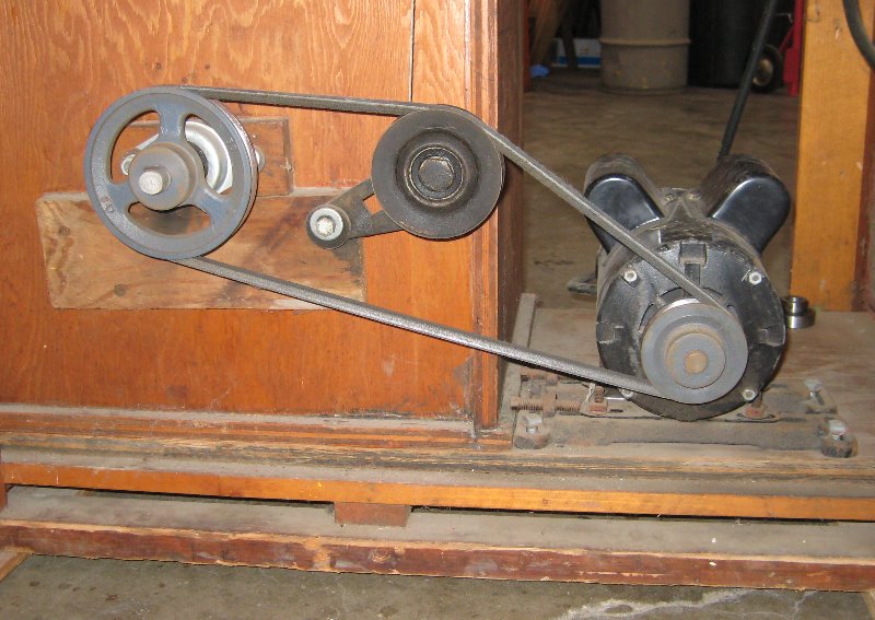
Blower
The motor, pulley, and belt arrangement. We suspect the motor is not original but are not sure.
The blower intake.
Top of the blower showing the outlet in the center of the photo.
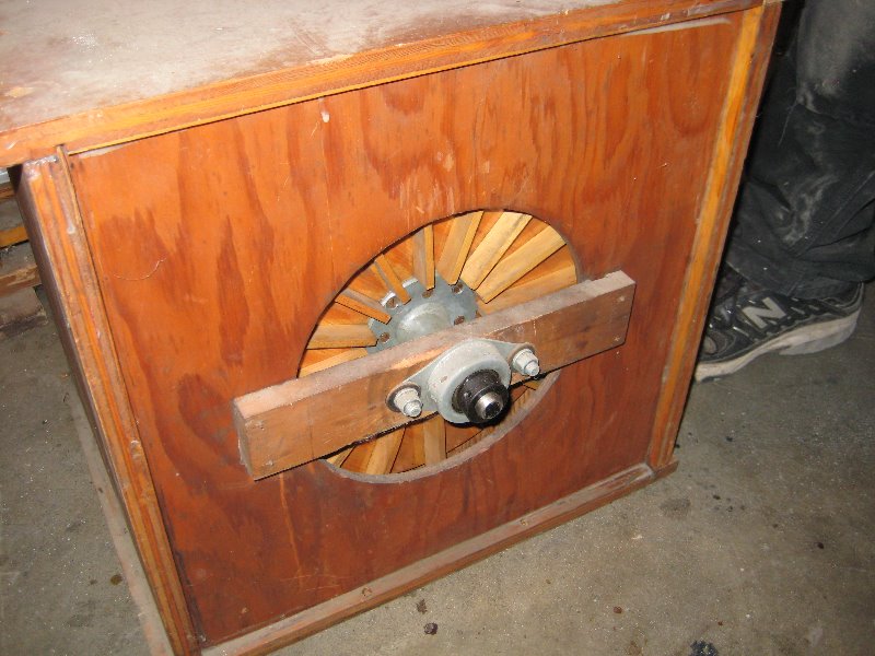
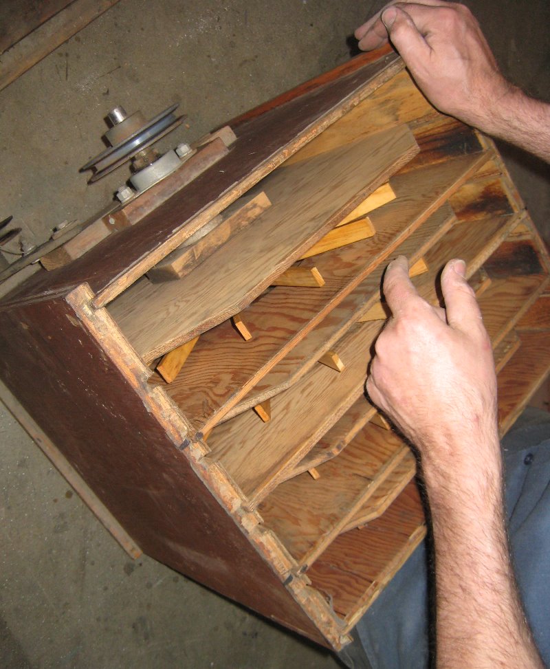
A top view looking into the blower with the cover removed. This is a four stage blower putting out 15 inches water column (about 0.5 psi). The fans are constructed of plywood with wood vanes mounted on cast metal hubs to a central axle and supported by bearings on the outside front and back of the unit.
More to come...More pictures and information will be posted as the work progresses. |